Automatically translated from Dutch by AI. Read the original
The architect's drawings and the structural engineer's calculation
The architect's choices explained and the structural engineer's calculation
The architect got to work, and in January 2026 we spoke on the phone several times and he came up with the following drawings. Several changes were made during this process and I’ll explain them with the drawings as well as I can.
Drawing #1
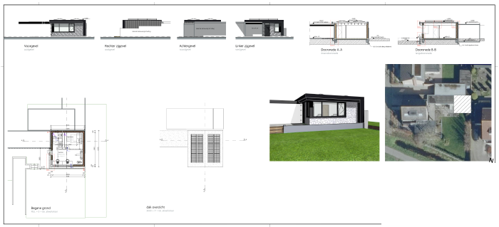
The layout stayed largely the same, and at this stage of the build it wasn’t very relevant to me yet. I wanted to get the structural engineer sorted so I could start on the foundation, and for that mainly the size and building materials mattered.
Roof height
For a flat roof you can build up to a maximum of 3 metres relative to the surrounding ground level. We went right up to those 3 metres because it lets us create a nice overhang on the visible sides of the building. A 50 centimetre overhang doesn’t count towards your built-up area. Notably, the garage is 2650 millimetres high, so we can let the overhang extend over it too. We had to remove part of the garage’s fascia boards and move the rainwater downpipe anyway. The rainwater drainage from one half of the garden office is thereby combined with that of the garage. The other half disappears into the continuous fascia board that runs down on the right of the building like a kind of column.
Size
After a lot of deliberation I decided to make the building smaller. We have raised beds to take up the height difference with the lawn. If the building stuck out further into the garden, it would create very odd shapes in those raised beds. On top of that, after a while I didn’t think it looked good visually next to the house. Fortunately I’d had quite a long time to think about it.
So the building should use the maximum space within the line of the raised beds. Effectively you then get a strip of gravel or soil of 200 mm between the bed edge and the building, and maybe even less if the thickness of the cladding turns out bigger.
Neighbours’ heights
You can see that with both neighbours I’m dealing with a total of 4 different heights. At one height I could connect the roof by letting the roofing felt hang down, but in most places a kind of gutter will be fixed halfway up my wall to minimise rain getting into the ventilation strip.
Drawing #2
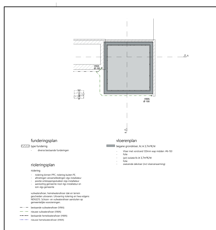
An interesting drawing, mainly for the structural engineer. I dug trial holes on every side to investigate two things: the foundations of the surrounding buildings and at what depth the sandy soil started. The architect took these points over. Although it says ‘incl. underfloor heating’, that isn’t suddenly the case. I believe it’s there to indicate that the screed can be a few centimetres thick and therefore put more load on it. The height difference with the garden was also a point for the structural engineer to take into account. That’s quite different from a standard build where everything around it is at the same level.
Drawings #3 and #4
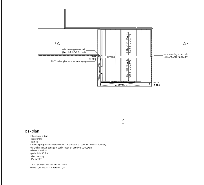
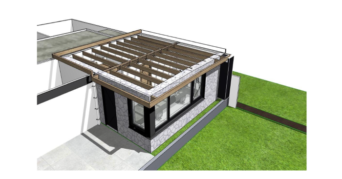
These actually already show part of the structural engineer’s result. This is the roof plan, and the architect already knew steel would have to go in. I did note an open point for myself here, because with the rainwater drainage I don’t yet know how I want to lay the fall of the roof. That could mean the HEA beam ends up positioned differently if I use it for the fall, but I’ll see when I come to plan the walls and roof.
You can also see the overhang clearly in the second photo.
Drawing #5
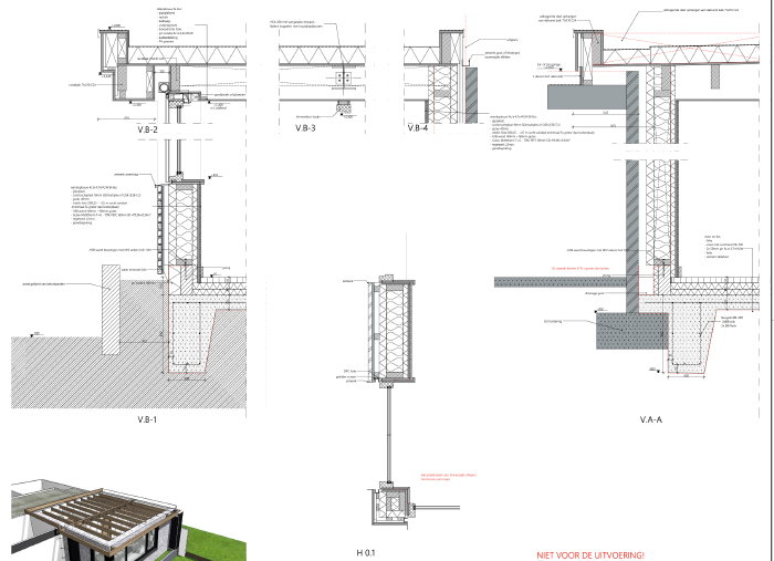
This one really shows several notable things.
Screens On V.B.-1 you can see nicely how the screens are hidden behind the fascia boards.
Waterproofing The red lines on V.B-1 and V.A.-A indicate the waterproofing between the timber frame and the Ytong blocks that are placed all around. It’s very important that you keep moisture from outside out of your foundation and don’t let it find a way up into your timber structure. With my choice not to connect to the surrounding buildings anywhere, we had a challenge here. We have to create a kind of gutter between the Ytong and the outer walls.
I have to say I got fairly scared when I learned about capillary action from Henrie. Moisture that moves upwards — think of holding a sugar cube just in your coffee and watching the coffee get sucked up. I now try to double-check this phenomenon at every step, because moisture problems in places I can barely reach don’t seem much fun to me!
Wall build-up The final wall build-up we have in mind is included here. It has been designed around the vapour-open principle: the most vapour-retarding layer (high SD value) on the warm side (inside), then decreasing towards the outside (low SD values).
Structural engineer
The structural engineer got to work with the drawings, and you get a report back that you understand little of. The following practical points came out of it.
- The bed edge is wide enough (150 mm blocks)
- 800 mm frost footing and 120 mm slab was fine — just follow the architect’s drawing
- 6 mm diameter reinforcement mesh with 150 mm spacing is sufficient
- HEA 200 in the roof is fine
Then a light bulb went on. Henrie from Zelfbouw Cursussen had told me several times: ‘on smaller projects I often use 2x 4 mm reinforcement mesh’. He does that because it’s usually perfectly fine that way, but the biggest gain is that you don’t have to make cages in your frost footing and then tie them to the mesh of the slab. You can bend 4 mm bar 90 degrees very easily, so you just let the ends hang down, bent over. I checked this with the structural engineer and it was fine.
The first real costs of the build have now been incurred!